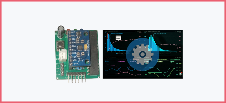
RUNNING THE SIC_MPU9250 SETUP APPLICATION
Some quick notes before running the GUI application:
- This would run on Windows, Linux (>Ubuntu 22.04), and Mac (as long as Python3 is installed on it)
- Please do not run on a micro-computer (e.g. Raspberry Pi), only a PC.
- Ensure you have
python3installed on your PC and alsopip - install python virtual environment. [pip3 install virtualenv //linux or mac] OR [pip install virtualenv //windows]
- Ensure also that the FTDI driver is installed on your PC. Follow this tutorial to do that if you have not.
HERE IS THE LINK TO THE FULL SETUP VIDEO PLAYLIST ON YOUTUBE: [LINK TO PLAYLIST]
You can easily clone/download and run the SIC_MPU9250 GUI setup application via a Python virtual environment following the instructions from its GitHub repo -> here.

1. RESETTING THE SIC_MPU9250 MODULE IMU PARAMETERS
Once you run the application and connect to the sic_mpu9250_driver module, you will see a page that allows you to choose the USB port to connect to the sic_mpu9250 module, select the right port, and click connect. Wait for about 10 seconds and you should have a successful connect dialog appear, click ok to continue. If not, refresh and try again to ensure you select the right port.
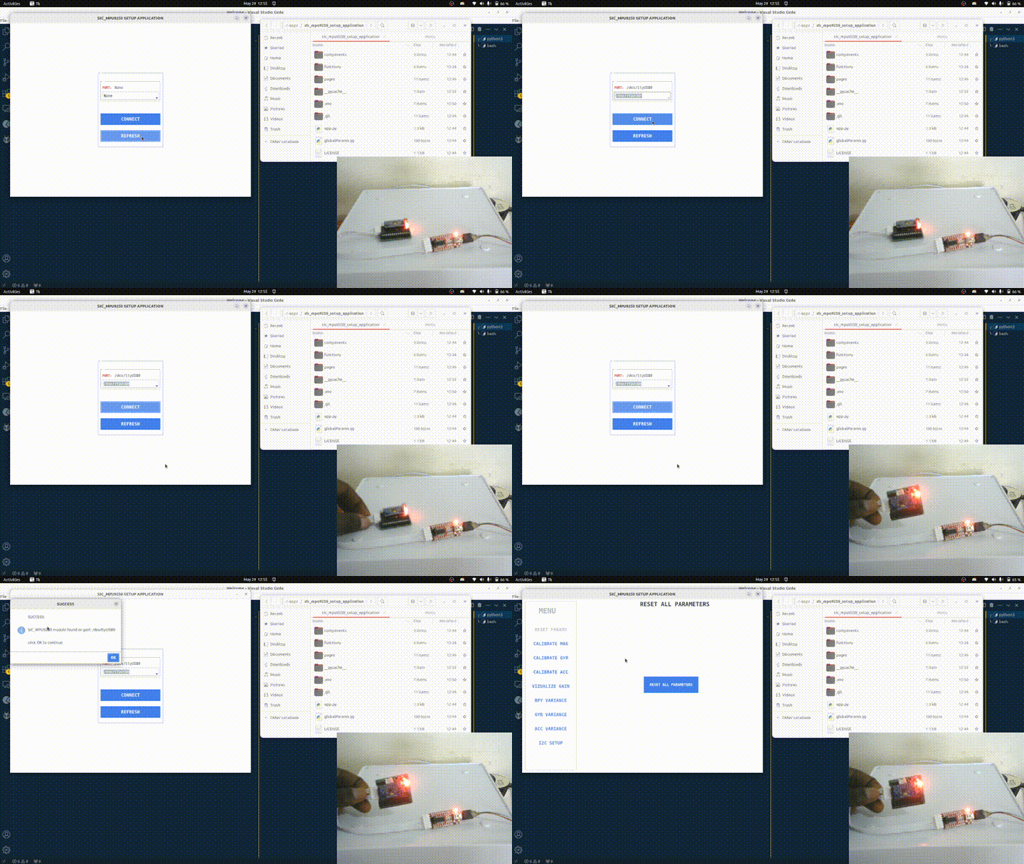
You should now see a menu on the left-hand side with different calibration, visualization, and other setup processes. If you’re setting up for the first time, reset all parameters by selecting the RESET PARAMS menu and clicking the RESET ALL PARAMETERS button to start the setup process with a clean slate. Once the reset is completed, the application will automatically close. Press the reset button on the sic_mpu9250 module.
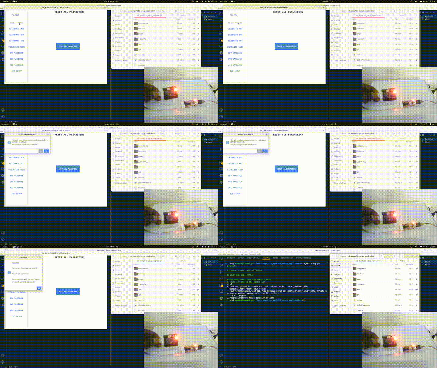
Once that is done, let’s get into the real deal – calibrating, setting Madgwick filter gain (with visualization), and computing covariances.
2. CALIBRATING THE SIC_MPU9250 MODULE
The calibration process has three parts: Magnetometer Calibration, Accelerometer Calibration, and Gyro Calibration. Open (run) the application and follow the steps below:
CALIBRATING THE MAGNETOMETER
This is the first step in the calibration process and the only calibration process that requires you to move and rotate the sic_mpu9250.
Select the CALIBRATE MAG menu and click the CALIBRATE MAG button. You should see a Matplotlib plot appear plotting points of different colors – red, blue, and green. Start rotating the IMU (or the container – e.g. robot – on which the IMU is mounted) slowly about the different (x, y, z) axis and see the plot update of the uncalibrated magnetometer data. Continue doing this until you see something like three balls not aligned with each other.
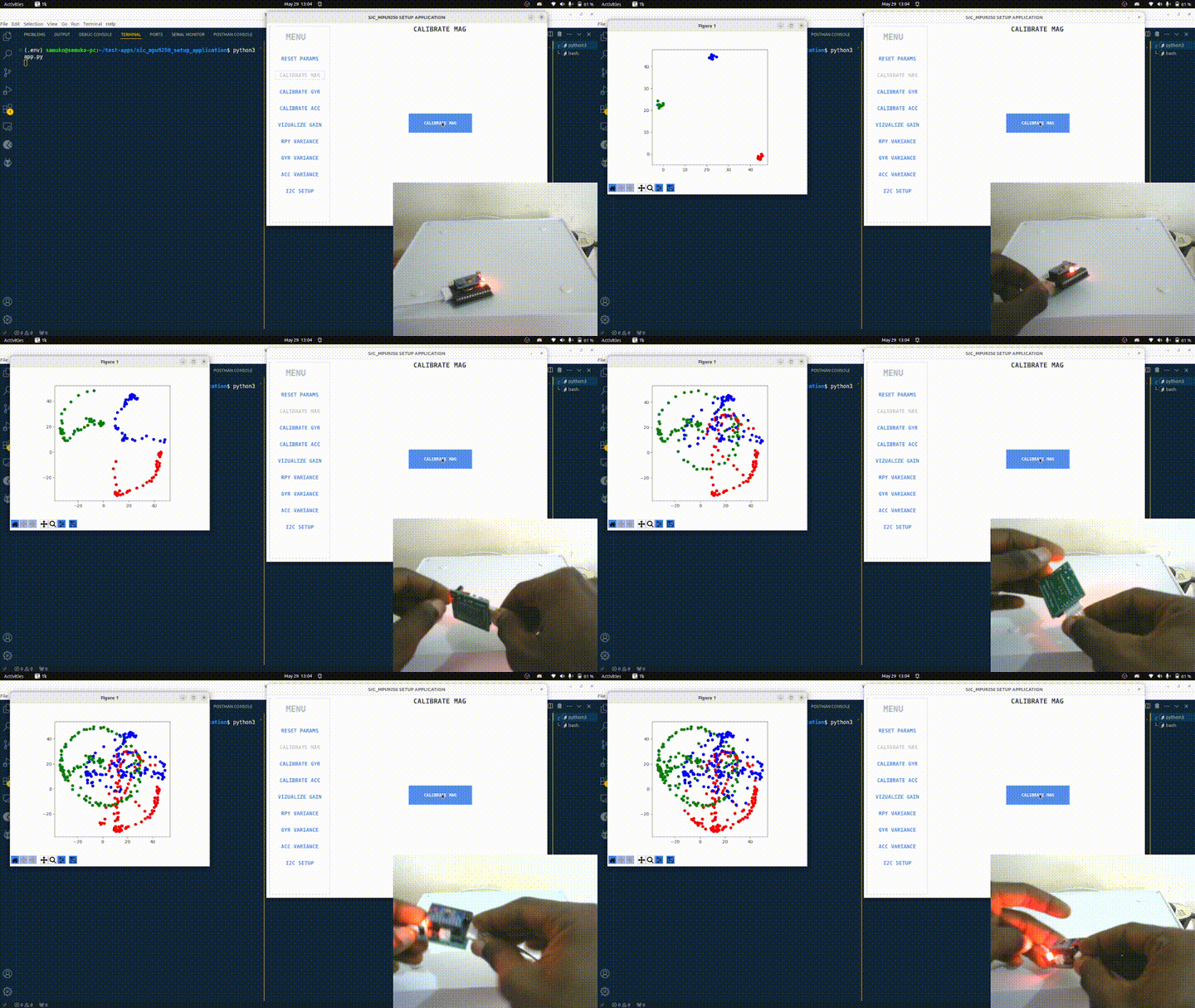
After this, click on the plot and the plot will be paused (please do not close the plot). On the terminal, you would see some values printed out which are the calibration parameters for the magnetometer. These values are automatically saved to the microcontroller on the sic_mpu9250 module (but you can copy the values somewhere else – e.g. a text editor – for reference or report purposes).
Then click on the plot again and it will begin to plot the calibrated magnetometer data. Rotate the IMU about the different axis again and you should see three balls forming which are aligned with each other.
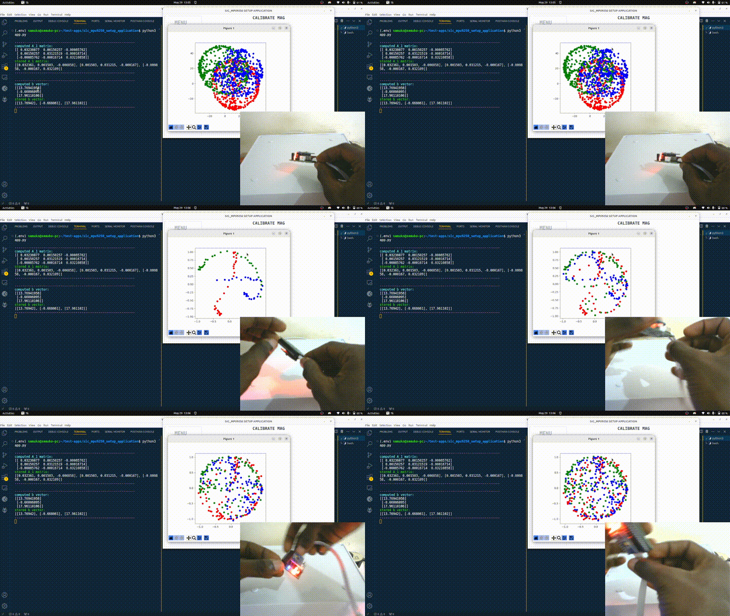
NOTE: If you do not see three balls forming or you see any of them forming a line (and not a ball or circle), you will have to repeat the magnetometer calibration process.
With this, I say congratulations because the magnetometer has successfully been calibrated. You can now close the plot (not the app).
CALIBRATING THE GYROSCOPE
Calibrating the gyroscope is very easy. Firstly, ensure the IMU is stationary – i.e. not being moved or disturbed – on a flat surface (If the IMU is mounted on a robot for example, just place the robot on a flat surface – e.g. on the floor, or on a flat table).
Now select the CALIBRATE GYR menu and click the CALIBRATE GYR button. You should see calibration status information being printed on the terminal. Wait until it is finished. Once it is completed, you should see a Matplotlib graph showing the uncalibrated and calibrated gyroscope data. Also, the calibration offset parameters would be printed on the terminal.
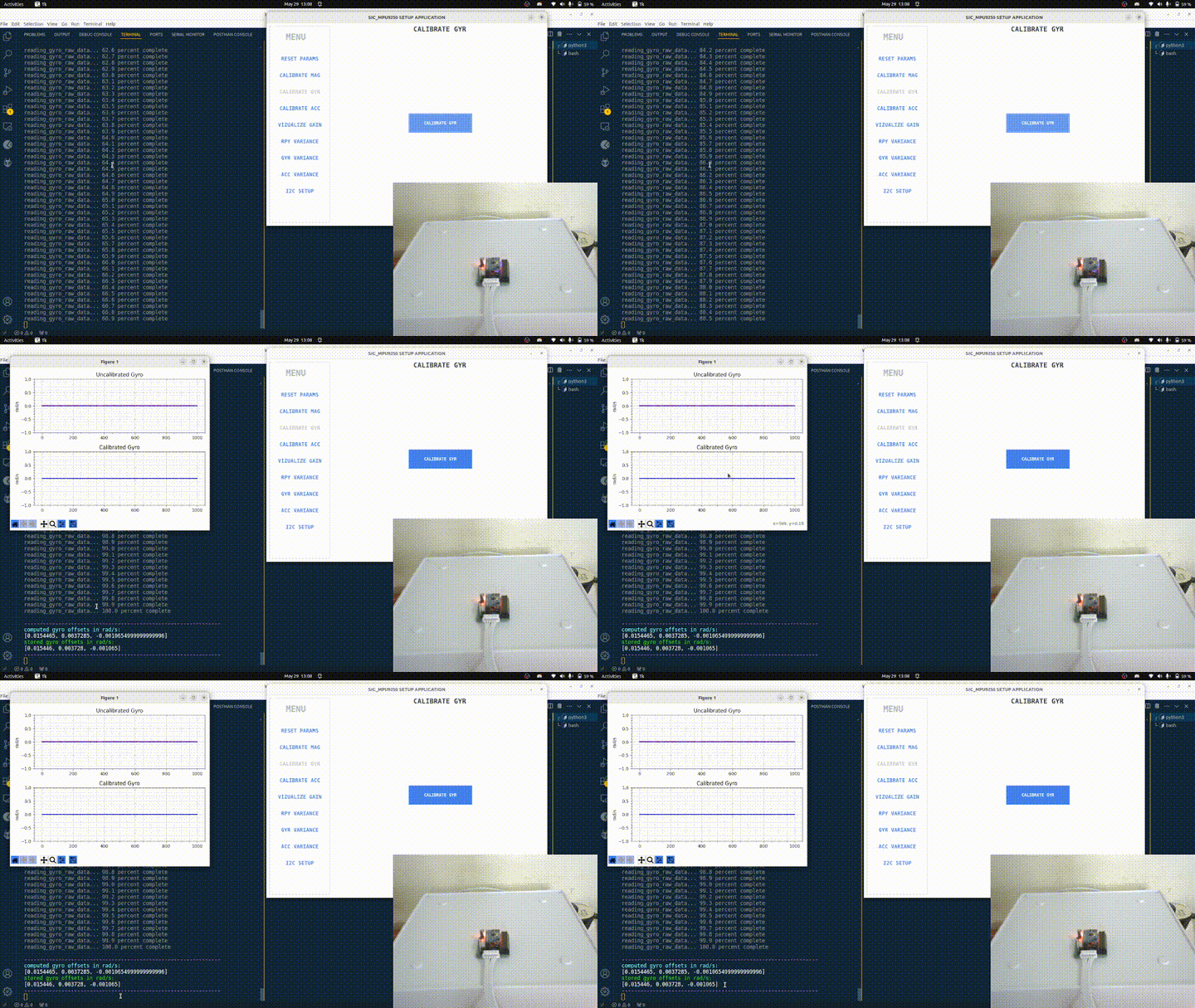
Remember that the gyroscope calibration offset values are automatically saved on the microcontroller on the sic_mpu9250 module (but you can copy the values somewhere else – e.g. a text editor – for reference or report purposes).
With this, I say congratulations because the gyroscope has successfully been calibrated. You can now close the plot (not the app).
CALIBRATING THE ACCELEROMETER
Calibrating the gyroscope is also very easy. Just follow the same steps as the gyroscope calibration above. You just need to select the CALIBRATE ACC menu and click the CALIBRATE ACC button.
Don’t forget to ensure the IMU is stationary – i.e. not being moved or disturbed – on a flat surface (If the IMU is mounted on a robot for example, place the robot on a flat surface – e.g. on the floor, or on a flat table).
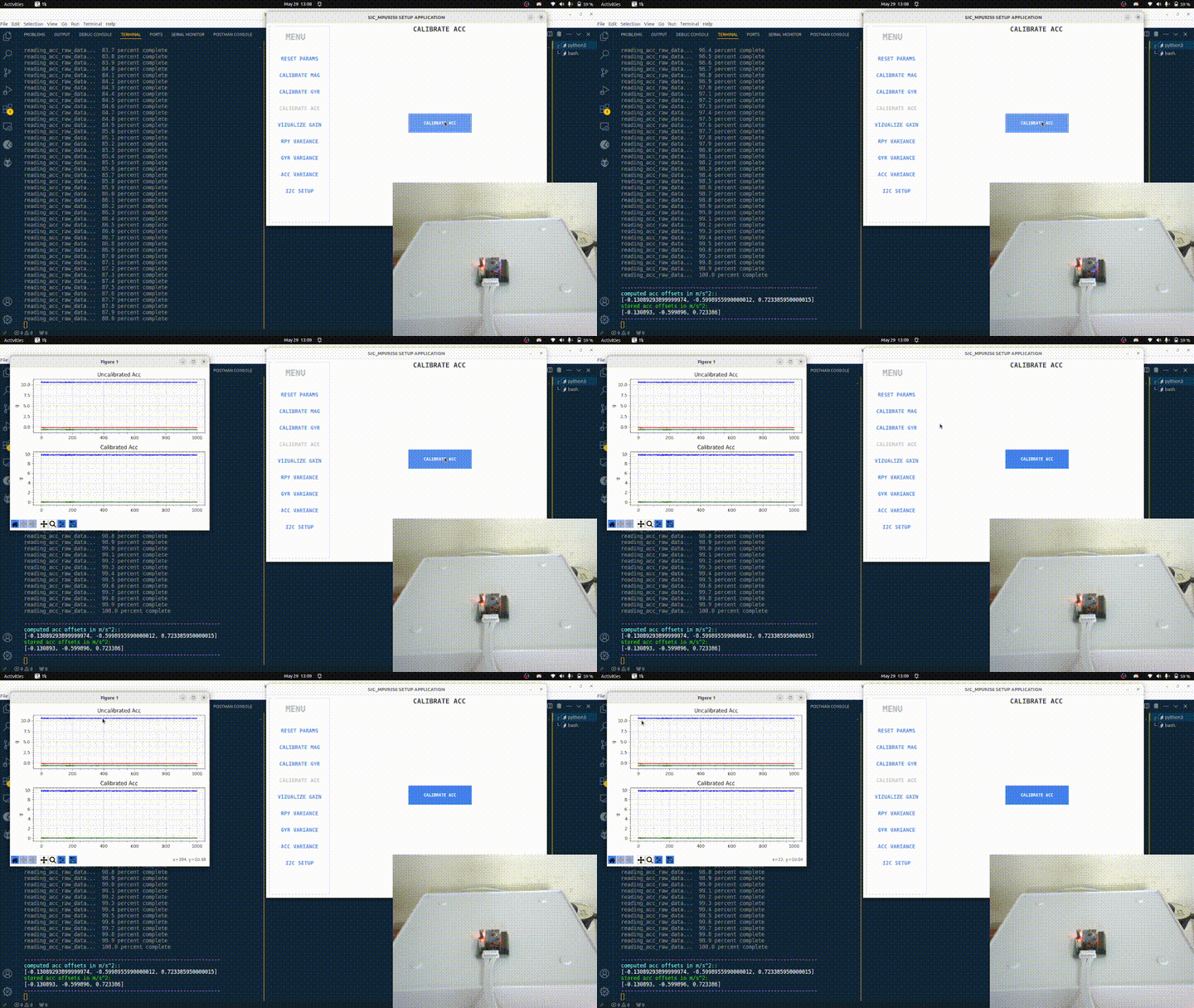
With this, I say congratulations because the accelerometer has successfully been calibrated. You can now close the plot (not the app).
3. SET THE MADGWICK FILTER GAIN (VISUALIZE THE IMU)
You need to do this step before going to the computing variances steps.
While the application is still open, open a web browser and place it side by side with the application (to make the process of toggling between setting the gain and visualizing easy).
Click the VISUALIZE GAIN menu, and a page that allows you to SET GAIN with a VISUALIZE IMU button will appear. Click the VISUALIZE IMU button and you should see the IMU visuals appear on the web browser.
Rotate the IMU (or your robot if it is mounted on it) and see the IMU visual transforms. Check if you are okay with the orientation convergence and noise. If you are not okay with it, adjust the gain value till you are satisfied.
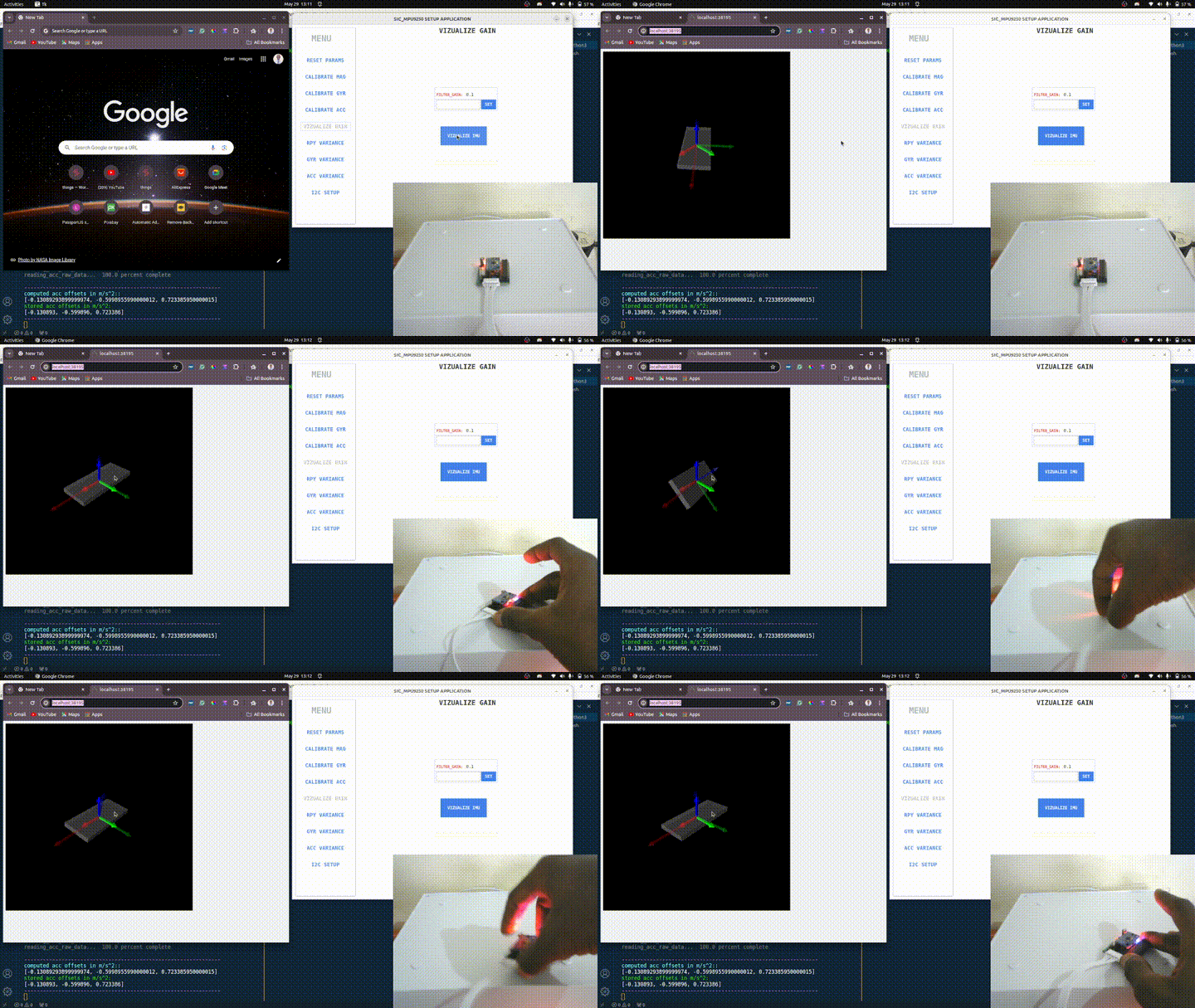
NOTE: A higher gain value leads to faster convergence and more noise while a lower gain value leads to slower convergence but smoother signal
The default gain value (0.1) is generally okay for most applications but feel free to adjust as you see fit for your application.
Once you are done, close the web browser tab where the IMU visual transform is being displayed. Once you close the browser, the sic_mpu9250_setup_application should also close.
4. SETUP AND COMPUTE THE VARIANCES
Reopen the application again. Follow the same process of calibrating the gyroscope and accelerometer above. Keep it in a stable and stationary position, select any of the RPY VARIANCE, GYR VARIANCE, or ACC VARIANCE menu, click the COMPUTE [RPY, GYR, or ACC] VARIANCE button, and see the computation status information being printed on the terminal. Once done, you should see the variance printed out on the terminal. Remember that the values are automatically saved on the microcontroller on the sic_mpu9250 module (but you can copy the values somewhere else – e.g. a text editor – for reference or report purposes).
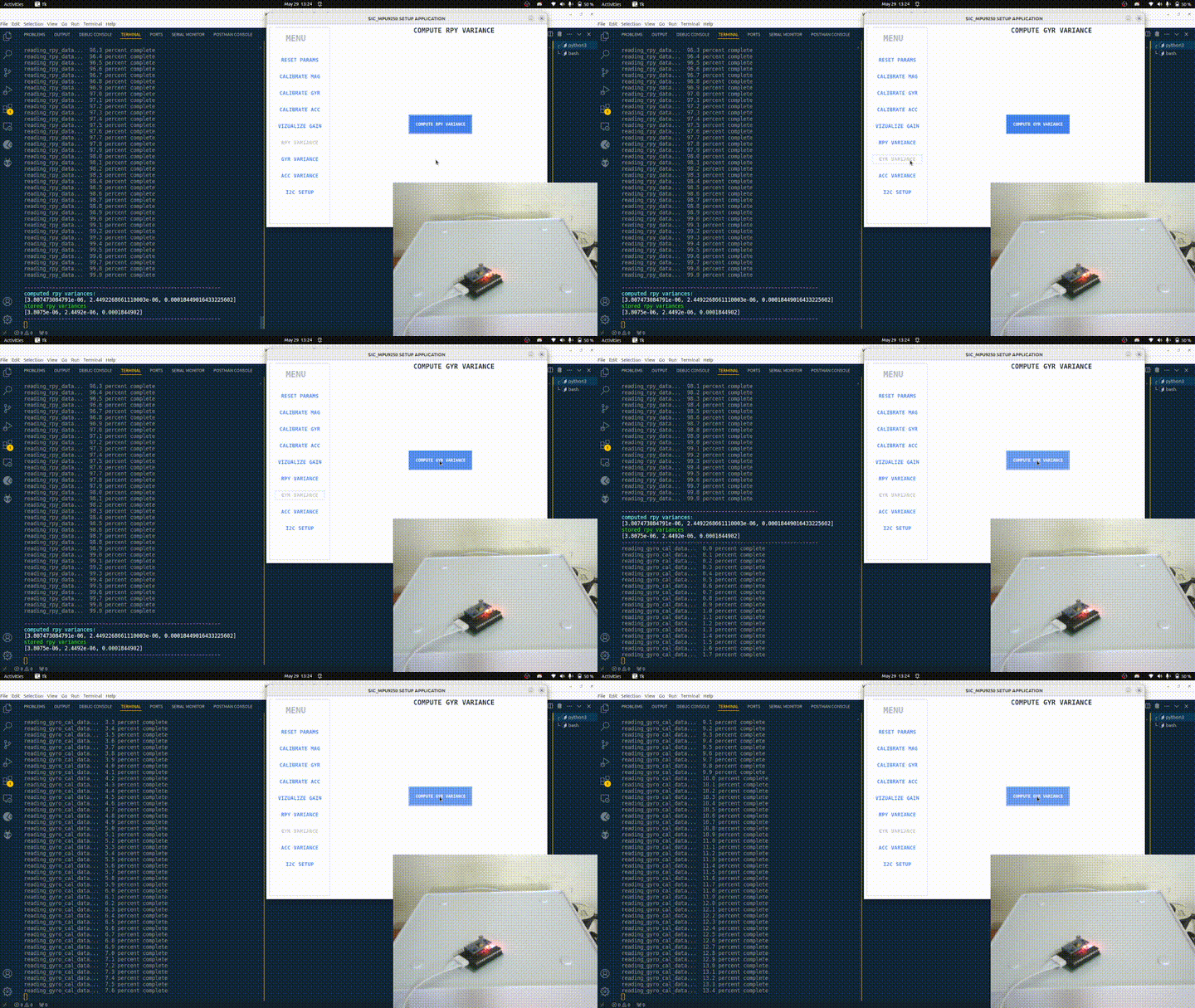
Do this for computing the orientation (RPY), rate (GYR), and acceleration (ACC) variance.
With this, I say congratulations because you have successfully set the sic_mpu9250 IMU and can now use it in your preferred project with its libraries.
5. I2C ADDRESS SETUP
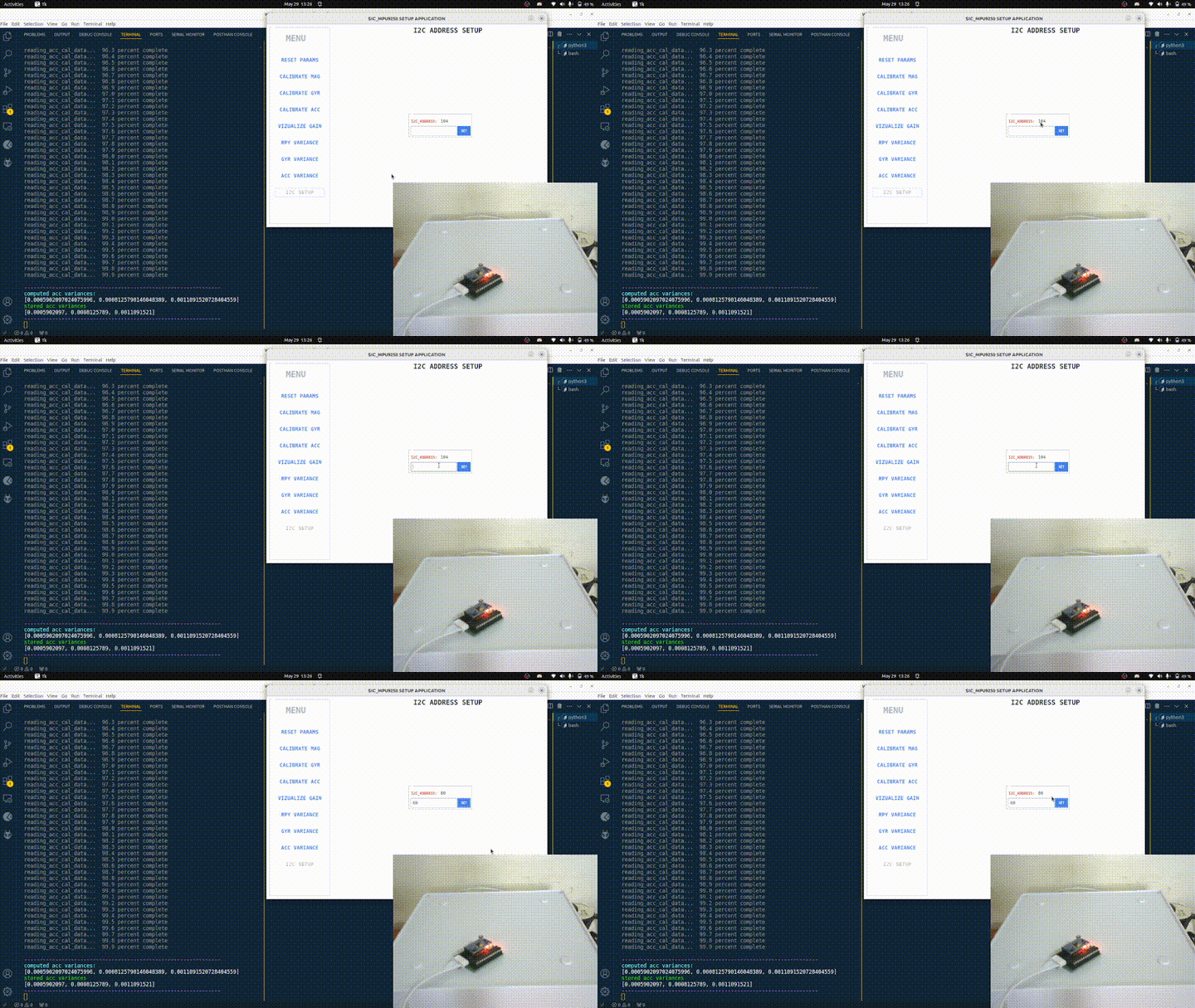
You can also set its i2c address for communication with Arduino microcontrollers.
Select the I2C SETUP menu and set your preferred address value (between 1 – 127). The default address value is 104 (i.e. 0x68).
Finally, don’t forget to deactivate the Python virtual environment after closing the application.
REFERENCES
- Magnetometer Calibration with the Ellipsoid Fit Algorithm – Tesla Labs
- 2D Graph Magnetometer visualization – Adafruit
- Gyroscope Calibration with Jupyter – Adafruit
- Reading Data From MPU9250 IMU – Bolder Flight
- IMU Data Visualization with Vpython – Paul McWhorter
- IMU Madgwick Filter Algorithm – CCNYRoboticsLab [Here’s a link to the Arduino Library I created from it – imu_madgwick_filter]
